Multi-Sensor LoRaWAN Node
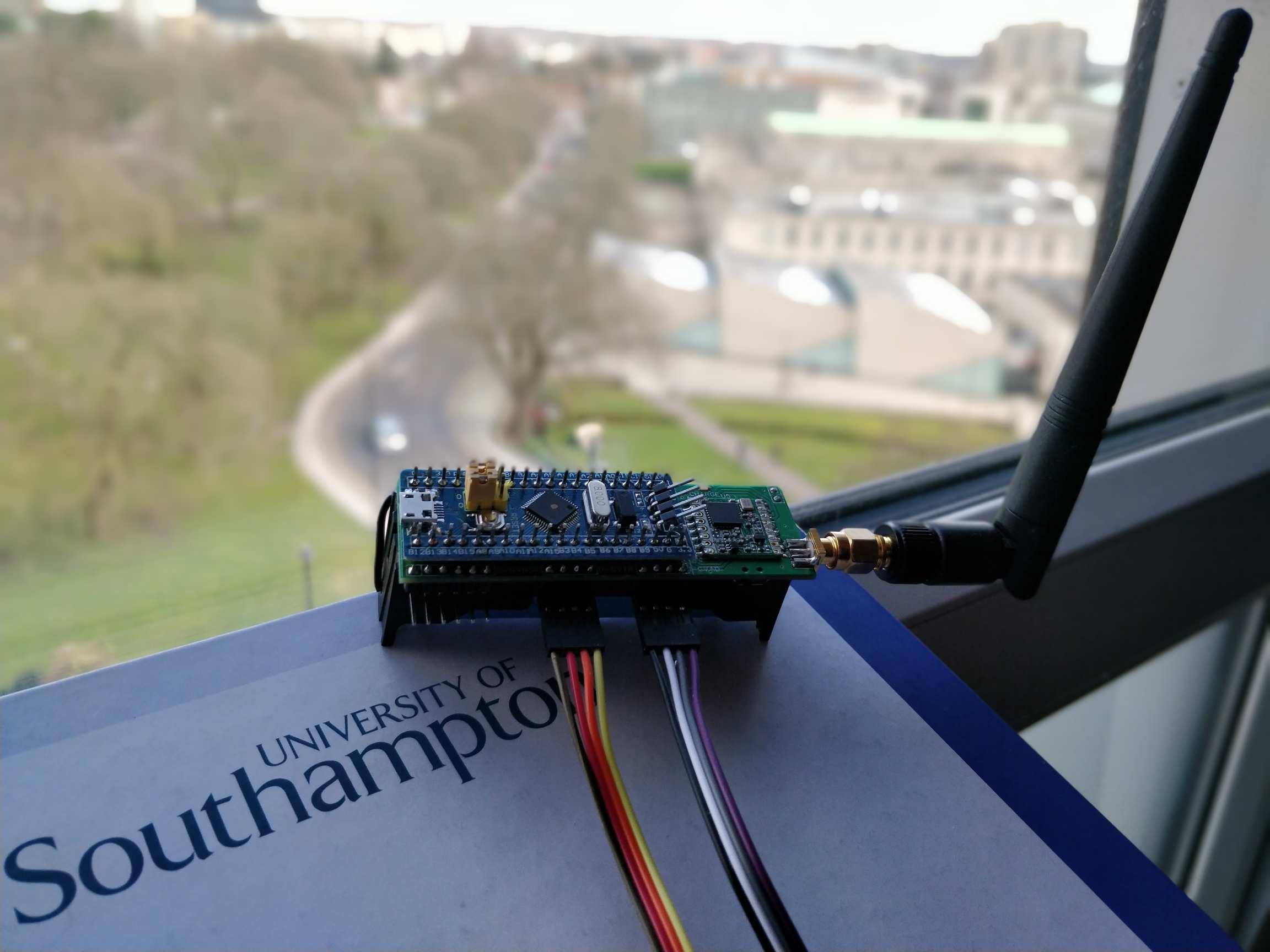
In March 2018, I built a multi-sensor LoRaWAN node with Matthew Wood that consists of a low-power STM32 “Blue Pill” board, a 9-DOF IMU, a GPS unit, and an ultra-long range transceiver with LoRa modem. The device reliably sent messages from the city centre to the university LoRaWAN gateways 4km away!
Low-Power Wide Area Networks (LPWANs) are providing the best known solutions to the challenges of creating smart interconnected cities. Amongst these Semtech’s LoRa Technology is incredibly promising and is already being put to good use! In Seoul, South Korea it’s being used to monitor waste bin capacity allowing the city to more intelligently plan waste collection routes as well as reduce the frequency of collection. This not only reduces costs but can dramatically improve the effectiveness of vital services. The Seoul Metropolitan Government announced plans in July 2019 to deploy 1,000 LoRaWAN-based gateways by 2022 to facilitate further expansion of their smart city capabilities.
LoRa has been shown to be effective across such large distances that it may even be capable of coordinating entire nations! A team managed to receive a message from a LoRaWAN transceiver from over 700km away!
What is LoRa?
LoRa is a proprietary physical layer protocol which uses chirp spread spectrum modulation. This enables it to reliably transmit data over long distances consuming minimal power in noisy environments. The physical layer is the first layer in the OSI model and is concerned with the low-level transmission of data bits between nodes in a network.
What is LoRaWAN?
LoRaWAN is an open MAC layer protocol maintained by the LoRa Alliance. The data link layer is the second layer in the OSI model and is concerned with transferring data between adjacent nodes in a wide area network. The MAC layer is a sublayer of the data link layer, and is primarily concerned with flow and access control to the shared channel. LoRaWAN networks have a star-of-stars topology as many nodes can communicate with many gateways which then relay messages to a central network server. LoRaWAN can also provide end-to-end encryption which is critical to many applications of the technology.
System Design

The system we built is shown in the figure above and is designed to collect, store, and serve data collected by the sensors. The multi-sensor device was encased in a unicorn outer shell, the antenna functioning as a suitable horn. The GPS device is capable of reporting the location of the device in addition to many other pieces of information such as the date and time. The IMU provides data related to the motion of the device. As a 9-DOF unit it is capable of detecting motion using a three axis accelerometer, three axis gyroscope, and a three axis magnetometer for a tilt-compensated compass.
The software stack includes libraries for each of the sensor devices, additional Arduino helper libraries, and the LMiC (LoraMAC-in-C) library, as well as the application code. The sensor libraries simplify the process of reading data from each of the devices. The LMiC library provides a near complete implementation of LoRaWAN and simplifies the process of transmitting and receiving data using the protocol.
Design Decisions
LoRa packets are limited to 64 bytes, 13 bytes of which cannot be used for the payload as they are reserved for other purposes. With only 51 bytes remaining it was necessary to devise a compact packet structure. It was decided that we should transmit only IMU, GPS, power and uptime data. It was not possible to include all of this data into one packet so it was necessary to alternate between IMU and GPS data during transmission periods.
By using a data block identifier it was possible to make a versatile packet structure that would accommodate this IMU and GPS data alternation. This versatility also meant that our packets could be responsive, only transmitting data if it is ready and valid, otherwise it is omitted from the packet.
STM Firmware
The firmware consists of a setup phase, a send job used to transmit data, and a loop which on each iteration invokes a single iteration of the LMiC OS runtime loop. The simplicity of this approach made it easy to test and customise at the later stages of the project. The code can be found here.

During the setup phase external I/O is configured, the LMiC OS and sensors are initialised, and the packet sequence number is set from the value stored in EEPROM. First the necessary serial lines are initialised for both debugging and the GPS unit. The LMiC library requires that three values are set for the LMiC session: the device address, the network session key, and the app session key. The device address is used by the LoRaWAN gateway to identify the LoRaWAN device. The network session key and application session key are used by the LoRaWAN gateway to authenticate the LoRaWAN device. These values were generated when registering the device on the university LoRaWAN gateway web console. Next the LoRaWAN channels are configured using the necessary European frequencies (eu868). Finally, the link check validation is disabled, the spreading factor is set to 12 as required by the University of Southampton LoRaWAN network, and the transmit power for uplink is set.
Transmission involves reading sensor data, constructing the packet, sending the packet, and then incrementing the packet sequence number ready for the next transmission. Reading the GPS sensor data requires polling of the serial line which then encodes read data into a data structure. The IMU is more straight forward, it provides a function that requests updated orientation data. The battery power is calculated by reading an analogue pin connected to a potential divider to appropriately scale the input voltage. This value is then scaled to provide a battery reading between 0 and 1023. To smooth out the battery power data reading five analogue readings are made and the average is used.
Constructing the packet consists of checking to see if a valid data reading has been made and if so including it in the packet. The data transaction is then set with the constructed payload and its length. To conserve power no acknowledgement of receipt is required, avoiding the need to resend unacknowledged data. Finally, a counter variable used to store the packet sequence number is incremented. This value is stored in EEPROM as it must persist between reboots in order for the LoRaWAN gateway to understand the order of the packets.
The processor then powers down for 50 seconds before powering back on and repeating the process. This provides us with readings approximately every 60 seconds.
LoRaWAN Gateway
When a data packet is sent and received by a LoRaWAN gateway it stores the information as a receive transaction (RX Info) alongside the payload. Each of the LoRaWAN gateways generates RX Info on receiving a packet, the information is then aggregated and can then be accessed through a central web service. RX Info consists of the channel used, coding rate, frequency, signal-to-noise ratio (LoRaSNR), received signal strength indicator (RSSI), a timestamp, the modulation used (in this case LoRa), bandwidth, spreading factor, bit rate, and the MAC address of the LoRaWAN gateway. The central web service enables you to register an HTTP integration that can then be used to extract this transaction information using HTTP POST requests. The code used to extract this information and store it in a database can be found here.
Conclusion
The system worked surprisingly well and showed that you can very reliably communicate small amounts of data over long distances using fairly inexpensive kit. Power consumption could continue to be improved however at its current rate it would last at least a week with continuous use.